This is the part three of my vaporizor writeup. You can find part one here and two here.
Warning: This post layout won't look very good due to it having many large photos and I haven't yet figured out how to display images smaller...
Process Description
So I left the writeup at the PCB layout.
In this post, I'll actually build the circuit board.
I'll be using the toner transfer method and ferric chloride to do the etching.
The basic process is to first create a mask.
A mask will "mask off" portions of the board where the traces are (or aren't). This is done via exporting the circuit board and printing onto a toner transfer paper. The toner is then transferred onto the copper clad board, covering the parts where the metal should remain. The board is left in a chemical bath for the etch, where the chemical will eat away the copper, leaving just the parts that are masked off. The toner is then removed to reveal an etched circuit board.
Here's a video showing the process (not by me):
I also experiment with using a photoresist mask in later projects.
The photoresist method is similar in the way it uses a mask, but it masks where the metal should be etched away instead (inverse). A photoresist material film is applied to the bare copper clad board. The material forms like a resin material when exposed to UV light. A reverse mask is printed on a transparent sheet and placed above the photoresist film to mask off the UV light. The unreacted photoresist is removed and the board is etched.
Preparation
I prepared:
- Copper clad board - A sheet of fiberglass or some material with one or both sides laminated with copper sheets
- Ferric Chloride - This will be our etchant
- Acetone - To remove the toner
- Toner transfer paper - Photopaper can also be used
- LaserJet printer (?) - I just hear that I should use laserjets because of how the ink is printed on the papers (element14). I've never tried it with a inkjet printer.
- Latex gloves - Oh yes those. We ARE dealing with chemicals. Although not particularly harmful, it is a good idea to wear them. They also prevent your hand from being covered in dark yellow stains. You're welcome to read the MSDS, if you'd like (MSDS).
- An iron - Like a clothing iron.
And some other useful things like:
- Some steel wool
- PCB cutter/shear
- Isopropyl Alcohol
- Drill press
- PCB vise
- Sharpie
- Beakers and containers for chemicals and etch bath
With that, let's get started.
Exporting the mask
First, I need to export the pcb design from KiCad.
I used the File -> Plot feature to export just the copper layer to PDF to scale.
DO NOT FORGET TO MIRROR
The pcb mask has to be mirrored since it will be transferred to another sheet.
I then printed the design onto a toner transfer paper.
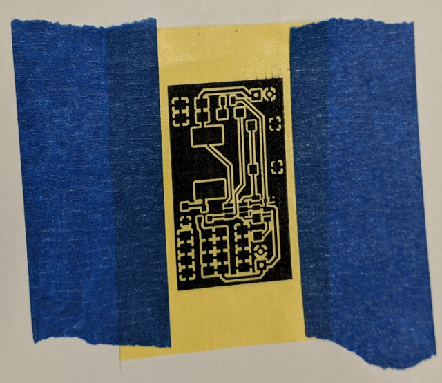
I wanted to save the toner paper, so I cut out a little piece and taped it where the circuit would be printed.
Transfer the mask
Before transferring, the copper clad board should be cleaned so that the toner sticks to the copper better.
I like the scrub it with the steel wood first, which cleans extraneous things stuck on the board and also makes it shiny :)
I then wipe it down with some isopropyl alcohol.

I then taped the paper face-down on the cleaned surface.

Pressing time!
I put the hot iron on top and pressed down on it firmly.
I pushed down fairly hard, but I've seen that pressing too hard will smear the toner slightly.

(I used the newspaper to protect the table from the heat)
After a few minutes, take the iron off the board and dip it into some cold water.
The tape can be removed and the wet paper can be rubbed off instead of peeling it to avoid peeling off the ink as well.

This one came out pretty much perfectly, excluding the slightly smudged top right corner, which doesn't matter too much.
If there are spots or traces that did not get completely covered, a sharpie can be used to cover it up.
Notice that I also cut the board to correct size.
Etch
There really isn't too much to etching.
I covered the back with some tape to not waste the chemical and since it will take a long time to eat away at the entire back layer.
I added another piece of tape so that I can easily check if finished and pick it up when the etch is done.
Besides that, I just poured some ferric chloride into the beaker and dropped it in.

After removing the toner with some acetone, there's a clean circuit etched onto the board.

I quickly inspected it using a multimeter to check if everything is connected/disconnected and then under a microscope to make little cuts on the copper where necessary.
Drilling
The circuit is done, but I do have some through-hold components, so I will need to drill some holes.
I don't remember what size drill bit I used (just used one that I found in the cabinet), but I put it in a vise and drilled some holes.


For a single-sided board like this, since I did not etch the back, all the pins may short through the back layer.
To fix this, I usually make a countersink on the back side with a larger drill bit.
I plunge just a little bit to try not to drill all the way through.
Hopefully, this shouldn't short with the pins.

The final pcb looks like this after cleaning up a bit.

Assembly

(I didn't have the surface mount LEDs yet)
Prototype
Before I etched and built the entire thing, I made a quick prototype to build and debug the code.
The same process was used.


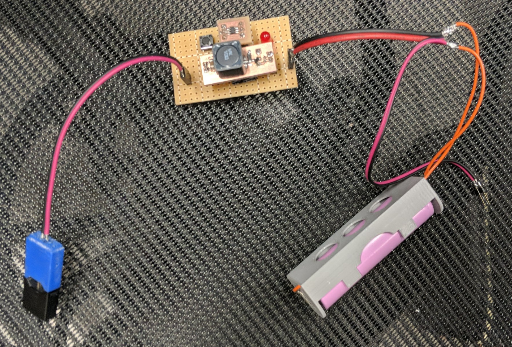
Final Product
Oh, you can see above the parts I 3D printed (battery holder + pod connector), the models for both of which are available in the GitHub repo (mechanical parts). I've also replaced the LEDs with the correct surface mount ones.
So, here's the final assembly.


I brought this to the guy who asked me to build it about a week later.
He had apparently forgotten all about it.
He just said, "oh... I bought a new one..."
Oh wells.
So uhh... That's it!
I've been procrastinating writing this blog for too long, so hopefully I pick it back up soon.
Not sure if I'll do another post about the BUUL firmware.
Anyways, thanks for reading.
73,
-Brian